
Required Components:
- Arduino UNO
- 5V-relay module
- DC motor
- IR sensor module
- Breadboard
- Connecting wires
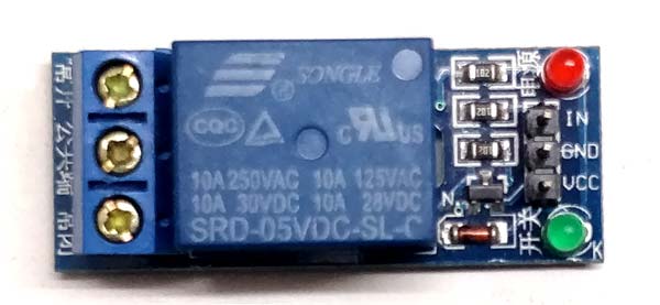 Relay Module
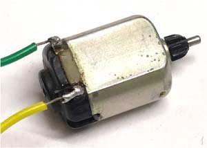 DC Motor
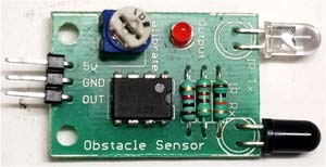 IR Sensor Module
Circuit Diagram and Explanation:
Circuit of this IR Sensor controlled DC Motor with Arduino is simple as shown below:

In circuit, IR sensor Module output pin is simple connected to the Pin 2 no of Arduino and Relay Module’s input is connected to Pin 7 no of Arduino. Further a DC Motor is connected to the Relay.
Working of IR controlled DC Motor with Arduino:
Working of this project is straight forward. Whenever there is some object in front of IR sensor, it will detect that and make the output pin high. IR sensor’s output pin is connected to Arduino, so Arduino will read it and activate the Relay module by making pin 7 high. As soon as relay is activated, it will turn on the DC motor.When there is no object near IR sensor, the output of IR sensor will remain low and DC motor will also remain in Off state. The sensitivity of IR Sensor can be adjusted using the potentiometer on the module itself. Sensitivity simply means the distance from which it can detect the object.
Complete Arduino Code and demo Video for the project are given below.
Code
void setup () {
pinMode (2, INPUT);
pinMode (7, OUTPUT);
Serial.begin (9600);
}
void loop () {
if (digitalRead (2) == 1)
{
Serial.println (digitalRead (2));
digitalWrite (7, HIGH);
}
else {
digitalWrite (7, LOW);
}
}


No comments