
Pulse Width Modulation:
What is PWM? PWM is a technique by using we can control the voltage or power. To understand it more simply, if you are applying 5 volt for driving a motor then motor will moving with some speed, now if we reduces applied voltage by 2 means we apply 3 volt to motor then motor speed also decreases. This concept is used in the project to control the voltage using PWM. (To understand more about PWM, check this circuit: 1 Watt LED Dimmer)% Duty cycle = (TON/(TON + TOFF)) *100 Where, TON = HIGH time of the square wave TOFF = LOW time of square wave
Now if the switch in the figure is closed continuously over a period of time then the motor will continuously ON during that time. If the switch is closed for 8ms and opened for 2ms over a cycle of 10ms, then the Motor will be ON only in the 8ms time. Now the average terminal over across the over a period of 10ms = Turn ON time/ (Turn ON time + Turn OFF time), this is called duty cycle and is of 80% (8/ (8+2)), so the average output voltage will be 80% of the battery voltage. Now human eye cannot see that motor is on for 8ms and off for 2ms, so will look like DC Motor is rotating with 80% speed.
In the second case, the switch is closed for 5ms and opened for 5ms over a period of 10ms, so the average terminal voltage at the output will be 50% of the battery voltage. Say if the battery voltage is 5V and the duty cycle is 50% and so the average terminal voltage will be 2.5V.
In the third case the duty cycle is 20% and the average terminal voltage is 20% of the battery voltage
Material Required
- Arduino UNO
- DC motor
- Transistor 2N2222
- Potentiometer 100k ohm
- Capacitor 0.1uF
- Breadboard
- Jumping Wires
Circuit Diagram

Working Explanation:
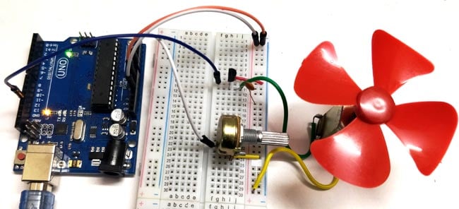
In this circuit, for controlling the speed of DC motor, we use a 100K ohm potentiometer to change the duty cycle of the PWM signal. 100K ohm potentiometer is connected to the analog input pin A0 of the Arduino UNO and the DC motor is connected to the 12th pin of the Arduino (which is the PWM pin). The working of Arduino program is very simple, as it reads the voltage from the analog pin A0. The voltage at analog pin is varied by using the potentiometer. After doing some necessary calculation the duty cycle is adjusted according to it.
For example, if we feed 256 value to the analog input, then the HIGH time will be 768ms (1024-256) and LOW time will be 256ms. Therefore, it simply means the duty cycle is 75%. Our eyes cannot see such high frequency oscillation and it looks like motor is continuously ON with 75% of speed. So that’s how we can control the speed using Potentiometer.
Code
int pwmPin = 12; // assigns pin 12 to variable pwm
int pot = A0; // assigns analog input A0 to variable pot
int c1 = 0; // declares variable c1
int c2 = 0; // declares variable c2
void setup () // setup loop
{
pinMode (pwmPin, OUTPUT);
pinMode (pot, INPUT);
}
void loop ()
{
c2 = analogRead (pot);
c1 = 1024-c2; // subtracts c2 from 1000 ans saves the result in c1
digitalWrite (pwmPin, HIGH);
delayMicroseconds (c1);
digitalWrite (pwmPin, LOW);
delayMicroseconds (c2);
}


No comments