
Project Overview:
This project demonstrates how to use a Force-Sensitive Resistor (FSR) to control multiple LEDs with an Arduino. The LEDs will light up based on the force applied to the FSR, creating a visual representation of the force level.
How It Works:
An FSR changes its resistance based on the amount of force applied to it. The Arduino reads this resistance as an analog value and turns on different LEDs based on the magnitude of the reading. Each LED corresponds to a specific range of force values.
Components List:
- Arduino Board (e.g., Uno, Nano, etc.)
- Force-Sensitive Resistor (FSR)
- 6 LEDs
- 220-ohm Resistors (for each LED)
- Jumper Wires
- Breadboard (optional)
- Power Supply (for Arduino)
Software List:
- Arduino IDE (Integrated Development Environment)
Circuit Diagram and Connection:
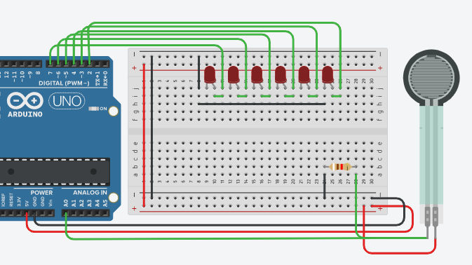
Connect the FSR to Analog Pin A0 on the Arduino.
Connect the anode (long leg) of each LED to Digital Pins 2 through 7 on the Arduino, and the cathode (short leg) to GND through a 220-ohm resistor.
Project Code:
int led1 = 2;
int led2 = 3;
int led3 = 4;
int led4 = 5;
int led5 = 6;
int led6 = 7;
int fsrreading;
void setup() {
pinMode(led1, OUTPUT);
pinMode(led2, OUTPUT);
pinMode(led3, OUTPUT);
pinMode(led4, OUTPUT);
pinMode(led5, OUTPUT);
pinMode(led6, OUTPUT);
}
void loop() {
fsrreading = analogRead(A0);
// Control LEDs based on FSR readings
digitalWrite(led1, fsrreading > 200 ? HIGH : LOW);
digitalWrite(led2, fsrreading > 450 ? HIGH : LOW);
digitalWrite(led3, fsrreading > 550 ? HIGH : LOW);
digitalWrite(led4, fsrreading > 650 ? HIGH : LOW);
digitalWrite(led5, fsrreading > 800 ? HIGH : LOW);
digitalWrite(led6, fsrreading > 900 ? HIGH : LOW);
}
Explanation of the Code:
Variable Declaration:
int fsrreading; is used to store the analog value from the FSR.
Setup Function:
pinMode(led1, OUTPUT); through pinMode(led6, OUTPUT); sets the LED pins as outputs.
Loop Function:
fsrreading = analogRead(A0); reads the analog value from the FSR.
Each digitalWrite statement controls an LED based on the FSR reading. The ternary operator (? :) is used to simplify conditional checks.
Test and Troubleshooting:
Testing: Upload the code to your Arduino. Apply different levels of force to the FSR and observe which LEDs light up.
Troubleshooting:
Ensure all LEDs and resistors are connected properly.
Verify the FSR is correctly connected to Analog Pin A0.
Check that the LEDs are functioning by testing them with a simple digitalWrite command.
Summary:
This project introduces how to use a Force-Sensitive Resistor with an Arduino to control multiple LEDs, providing a visual indication of force levels. It demonstrates basic sensor reading and LED control, which are fundamental concepts in electronics and programming.


No comments