
Project Overview:
This project involves using a tilt sensor to control an LED. The LED turns on or off based on the orientation of the tilt sensor. This simple project can be used to create a basic tilt-sensitive device.
Components List:
- Arduino Uno (or compatible)
- 1 x Tilt Sensor
- 1 x LED
- 1 x 220Ω Resistor (for the LED)
- Breadboard and Jumper Wires
Circuit Connection:
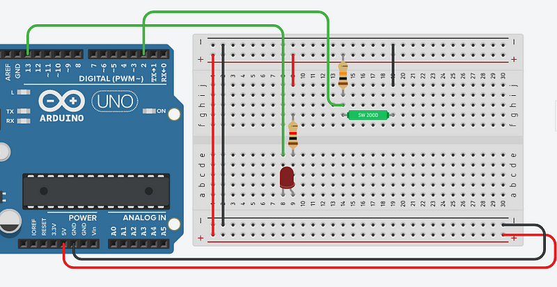
- Tilt Sensor:
- Connect one side of the tilt sensor to digital pin 2 on the Arduino.
- Connect the other side to GND.
- LED Setup:
- Connect the positive leg (anode) of the LED to digital pin 13.
- Connect a 220Ω resistor from the negative leg (cathode) of the LED to GND.
Project Code:
int tilt = 2;       // Pin connected to tilt sensor
int led = 13;       // Pin connected to LED

void setup(){
  pinMode(tilt, INPUT);    // Set tilt sensor pin as input
  pinMode(led, OUTPUT);    // Set LED pin as output
}

void loop(){
  int reading = digitalRead(tilt);  // Read the state of the tilt sensor

  if(reading) {
    digitalWrite(led, LOW);    // Turn off the LED if tilt sensor is triggered
  } else {
    digitalWrite(led, HIGH);   // Turn on the LED if tilt sensor is not triggered
  }
}
Explanation of the Code:
- Setup Function:
- Configures the tilt sensor pin as an input and the LED pin as an output.
- Loop Function:
- Continuously reads the state of the tilt sensor.
- If the sensor is triggered (i.e., it detects a tilt), the LED is turned off.
- If the sensor is not triggered (i.e., it’s in a stable position), the LED is turned on.
Summary:
This project demonstrates how to use a tilt sensor to control an LED. When the sensor is tilted, the LED turns off, and when the sensor is upright, the LED remains on. This simple setup can be expanded into more complex projects, such as a tilt-sensitive alarm or a motion-triggered light.


No comments