
Project Overview:
This project demonstrates how to control a robot’s movement using two sensors to detect obstacles or line-following signals. The Arduino reads values from the sensors and adjusts the motor outputs to move the robot forward, turn, or stop based on the sensor readings.
How It Works:
The robot uses two sensors to detect its surroundings. Depending on the sensor readings, the Arduino controls the motors to make the robot move forward, turn left, turn right, or stop. This project involves reading analog values from sensors and using them to drive motor control pins with appropriate logic.
Components List:
Left Sensor (e.g., IR sensor or line sensor) (Use the IR Receiver Module link if it's the most relevant)
Right Sensor (e.g., IR sensor or line sensor) (Use the IR Receiver Module link if it's the most relevant)
Power Supply (for motors) (If you have a specific link for power supplies, you might want to include that instead)
Software List:
Arduino IDE (Integrated Development Environment)
Circuit Diagram and Connection:
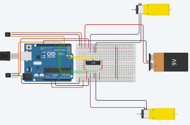
Connect the output of the left sensor to Analog Pin 3 on the Arduino.
Connect the output of the right sensor to Analog Pin 4 on the Arduino.
Connect the control pins for Motor 1 and Motor 2 to the specified digital pins on the Arduino.
Connect the motors to the motor driver module and ensure the power supply is connected to the motor driver.
Project Code:
#define LEFT_SENSOR 3 // Pin connected to the left sensor
#define RIGHT_SENSOR 4 // Pin connected to the right sensor
#define Motor14 1 // Pin connected to motor 1 (control pin 1)
#define Motor15 0 // Pin connected to motor 1 (control pin 2)
#define Motor17 5 // Pin connected to motor 2 (control pin 1)
#define Motor18 6 // Pin connected to motor 2 (control pin 2)
void setup() {
// Set Timer 0 for PWM (Pulse Width Modulation) used for motor speed control
TCCR0B = TCCR0B & B11111000 | B00000010;
// Start serial communication for debugging (optional)
Serial.begin(9600);
// Set sensor pins as inputs
pinMode(LEFT_SENSOR, INPUT);
pinMode(RIGHT_SENSOR, INPUT);
// Set motor control pins as outputs
pinMode(Motor14, OUTPUT);
pinMode(Motor15, OUTPUT);
pinMode(Motor17, OUTPUT);
pinMode(Motor18, OUTPUT);
}
void loop() {
int leftSensorValue = analogRead(LEFT_SENSOR); // Read analog value from left sensor
int rightSensorValue = analogRead(RIGHT_SENSOR); // Read analog value from right sensor
// Print sensor readings for debugging (optional)
Serial.print("LEFT_SENSOR = ");
Serial.println(leftSensorValue);
Serial.print("RIGHT_SENSOR = ");
Serial.println(rightSensorValue);
// Call the rotation function to control motor movement based on sensor readings
rotation(leftSensorValue, rightSensorValue);
}
void rotation(int leftValue, int rightValue) {
// Forward (both sensors see white - high sensor readings)
if (leftValue >= 800 && rightValue >= 800) {
digitalWrite(Motor14, HIGH);
digitalWrite(Motor15, LOW);
digitalWrite(Motor17, HIGH);
digitalWrite(Motor18, LOW); // Set motors to move forward
}
// Right turn (left sensor sees black - low sensor reading, right sensor sees white)
else if (leftValue <= 800 && rightValue >= 800) {
digitalWrite(Motor14, LOW);
digitalWrite(Motor15, HIGH);
digitalWrite(Motor17, HIGH);
digitalWrite(Motor18, LOW); // Set motors to turn right
}
// Left turn (left sensor sees white, right sensor sees black)
else if (leftValue >= 800 && rightValue <= 800) {
digitalWrite(Motor14, HIGH);
digitalWrite(Motor15, LOW);
digitalWrite(Motor17, LOW);
digitalWrite(Motor18, HIGH); // Set motors to turn left
}
// Stop (both sensors see black - low sensor readings)
else {
digitalWrite(Motor14, LOW);
digitalWrite(Motor15, LOW);
digitalWrite(Motor17, LOW);
digitalWrite(Motor18, LOW); // Stop motors
delay(400); // Wait for 400 milliseconds
// Short forward movement to help escape from a centered position
digitalWrite(Motor14, HIGH);
digitalWrite(Motor15, LOW);
digitalWrite(Motor17, HIGH);
digitalWrite(Motor18, LOW); // Short forward movement
delay(400); // Wait for 400 milliseconds
}
}
Explanation of the Code:
Pin Definitions: Defines pins for sensors and motor controls for easy reference.
Setup Function:
Configures Timer 0 for PWM control, which affects motor speed.
Initializes serial communication for debugging.
Sets sensor pins as inputs and motor control pins as outputs.
Loop Function:
Reads sensor values from the left and right sensors.
Prints sensor values to the Serial Monitor for debugging.
Calls the rotation() function to adjust motor control based on sensor readings.
Rotation Function:
Controls motor direction based on sensor values to move forward, turn left, or right, or stop and perform a short forward movement if needed.
Test and Troubleshooting:
Testing: Upload the code to the Arduino and place the sensors on the robot. Adjust the robot's path and observe the motor behavior based on sensor readings.
Troubleshooting:
If the robot does not move as expected, check the sensor connections and ensure they are correctly positioned.
Verify that the motor driver module and motors are properly connected and powered.
Check the serial output to confirm sensor readings and ensure the logic in the rotation() function is correct.
Summary:
You've successfully created a robot movement control system based on sensor feedback using Arduino. This project introduces key concepts in sensor integration and motor control, setting the stage for more complex robotics and automation projects.


No comments