
Project Overview:
In this project, you'll learn how to use an analog sensor with Arduino to control the brightness of an LED. This is a fundamental project that demonstrates how to read analog values and use them to adjust output signals, making it perfect for understanding sensor integration and PWM (Pulse Width Modulation) control.
How It Works:
The Arduino reads the analog input from a sensor (like a potentiometer) connected to analog pin A0. It then maps this sensor value to a range suitable for PWM and writes it to an LED connected to digital pin 9. This allows you to adjust the LED’s brightness based on the sensor input.
Components List:
- Arduino Board (e.g., Uno, Nano, etc.)
- Analog Sensor (e.g., Potentiometer)
- LED
- Resistor (220 ohms, for the LED)
- Jumper Wires
- Breadboard (optional)
- USB Cable (for connecting Arduino to the computer)
Software List:
Arduino IDE (Integrated Development Environment)
Circuit Diagram and Connection:
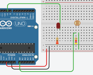
Connect the VCC pin of the analog sensor to the 5V pin on the Arduino.
Connect the GND pin of the analog sensor to the GND pin on the Arduino.
Connect the OUT pin of the analog sensor to analog pin A0 on the Arduino.
Connect the anode (longer leg) of the LED to digital pin 9.
Connect the cathode (shorter leg) of the LED to the GND through a 220-ohm resistor.
Project Code:
int sensorValue = 0;
void setup() {
pinMode(A0, INPUT);
pinMode(9, OUTPUT);
Serial.begin(9600);
}
void loop() {
sensorValue = analogRead(A0);
analogWrite(9, map(sensorValue, 0, 1023, 0, 255));
delay(100);
}
Explanation of the Code:
Variable Initialization: int sensorValue = 0; declares a variable to store the sensor value.
Setup Function:
pinMode(A0, INPUT); configures the analog pin A0 as an input.
pinMode(9, OUTPUT); configures digital pin 9 as an output.
Serial.begin(9600); initializes serial communication for debugging.
Loop Function:
sensorValue = analogRead(A0); reads the analog value from pin A0.
analogWrite(9, map(sensorValue, 0, 1023, 0, 255)); maps the sensor value (0-1023) to a PWM value (0-255) and writes it to pin 9, adjusting the LED brightness.
delay(100); adds a small delay to stabilize the readings.
Test and Troubleshooting:
Testing: Upload the code to your Arduino and turn the knob on the analog sensor (e.g., potentiometer). The LED's brightness should change accordingly.
Troubleshooting:
If the LED does not change brightness, check your wiring connections.
Ensure the analog sensor is correctly connected to analog pin A0.
Verify that the resistor is properly connected in series with the LED.
Summary:
You’ve successfully created a project that adjusts an LED’s brightness based on an analog sensor's input using Arduino. This project introduces essential concepts of analog-to-digital conversion and PWM, providing a solid foundation for more advanced Arduino projects involving sensors and actuators.


No comments