
Wireless Water Level Indicator Using Ultrasonic sensor & Arduino is an amazing and very useful project. The objective of this project is to notify the user the amount of water that is present in the overhead water tank. This project can be further enhanced to control the water level in the tank by turning it ON, when the water level is LOW, and turning it OFF when the water level is HIGH. Thus, the Arduino water level indicator helps in preventing wastage of water in overhead tank. This project is wireless so, it is easy to install and it can work up to 100 meters.
In this project two circuits are used: a transmitter circuit and a receiver circuit. The transmitter circuit makes use of an ultrasonic sensor to measure the water level in terms of distance. This data is sent to the receiver circuit using RF communication. The water level is shown in terms of percentage on a 16×2 LCD module, which is connected to receiver circuit.
Components
Components Specification Quantity
Arduino Nano 2
Ultrasonic Sensor HC-SR04 1
RF Transmitter Receiver Pair ASK 433 1
LCD 16x2 1
Preset 10K 1
Switch DPDT (PCB Mount) 2
Battery 9 Volt 2
Battery Holder 2
Arduino Water Level Indicator Circuit
In this project two circuits are used
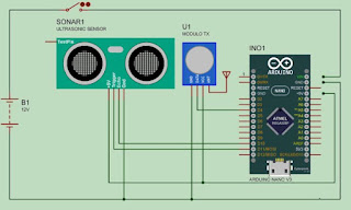
Transmitter Circuit –
Transmitter circuit is shown in the figure below. Fig1, in this circuit an Ultrasonic sensor is connected to pin D9 and D10 pin of Arduino. Ultrasonic sensor is powered by Vcc and GND pin, these pins are connected to Vcc and GND pin of the Arduino. The measured data is transmitted by RF transmitter. RF transmitter’s data pin is connected to D4 pin of Arduino Nano. RF transmitter’s Vcc and GND pins are connected to Vcc and GND pins of the Arduino. In this transmitter circuit an Antenna is used which is connected to ANT pin of RF transmitter, whole circuit is powered by 9 volt battery. The battery is connected to Vin and GND pin of Arduino.

Receiver Circuit
– In the receiver Circuit, RF Receiver is used for receiving data from the transmitter. Data pin of RF Receiver is connected to D4 pin of Arduino. Water level is shown on LCD and LCD is connected to Arduino from pin D4 to D9. LCD is powered by Vcc and GND pin using the Arduino, the contrast of LCD is changed by moving the preset, which is connected to pin 3 of LCD. Receiver circuit is powered by a 9 Volt battery through a switch, which is connected between Vcc and GND pin of the Arduino. Circuit is shown in the figure below.
Code
#include <RCSwitch.h>
#include <Ultrasonic.h>
Ultrasonic ultrasonic(11,10);
RCSwitch mySwitch = RCSwitch();
int i;
void setup() {
mySwitch.enableTransmit(4);
}
void loop() {
i = ultrasonic.Ranging(CM);
mySwitch.send(i, 24);
delay(100);
}
Program for Water Level Controller (Receiver)
#include <RCSwitch.h>
#include <LiquidCrystal.h>
LiquidCrystal lcd(4, 5, 6, 7, 8, 9);
RCSwitch mySwitch = RCSwitch();
float level;
int Hval=2;
int Lval=12;
int BUZZER = 10 ;
void setup() {
mySwitch.enableReceive(0);
lcd.begin(16, 2);
lcd.print("WATER LEVEL INDI");
pinMode(BUZZER,OUTPUT);
}
void loop() {
if (mySwitch.available()) {
level = mySwitch.getReceivedValue();
level = level/(Lval - Hval);
level = level*100;
if (level>100) {level=100;}
lcd.setCursor(0, 1);
lcd.print("LEVEL ");
lcd.print(level);
lcd.print(" % ");
mySwitch.resetAvailable();
}
digitalWrite(BUZZER,HIGH);
if (level > 99) {digitalWrite(BUZZER,HIGH); delay(100); digitalWrite(BUZZER,LOW); delay(100);}
else {digitalWrite(BUZZER,LOW);}
}
How to Attach Library
Download the library file from the linkExtract the file rc-switch-master.
Copy the folder inside rc-switch-master folder.
Paste the folder at location Documents> Arduino> library.
Close the Arduino IDE software (if opend).
Open the Arduino IDE.
Click on file >Example
If library is attached, you can see the rc-switch-master in Example list.
Transmitter
In the coding of the transmitter side, two header files are used. First is RCSwitch.h, which is used for RF transmitter and the second is Ultrasonic.h, which is used for the ultrasonic sensor.
Now pins of ultrasonic sensor is declared by the name ultrasonic in line 4, pin11 is Trig and pin10 is Echo. In the line 5 RCSwitch is declared for the transmitter by name “mySwitch”. In the line 7 an integer is declared by the name “i”.
In the void setup Transmitter is enabled by function “mySwitch.enableTransmit(4)”, where transmitter’s data pin is connected to pin D4 of the Arduino.
In the void loop, the distance is measured by function “ultrasonic.Ranging(CM)” and it is assigned in integer “I”, this distance is measured in centimeters.
In the line 15, the measured distance is transmitted by function “mySwitch.send(i, 24)”, where “i” is the distance and 24 is the bit format. After all “delay” of 100 milliseconds are used, which means Arduino sends the data after every 100 milliseconds.
Receiver
In the receiver side, two header files are used, The first is “RCSwitch.h” which is used for RF communication between the Transmitter and the Receiver and the second is “LiquidCrystal.h”, which is used for LCD display.
In the line 4, Arduino pins are declared, which are connected to LCD. Total 6 pins are connected to Arduino that are D4, D5, D6, D7, D8, D9. In the line 5, “RCSwitch” is declared by the name “mySwitch”.
In the line 7, a float is declared by the name “level”, which shows the water level and in the line 9 and 10 two integers are declared by name “Hval” and “Lval” where, “Hval” is the upper value of water level (distance from ultrasonic sensor) and “Lval” is the Lower value of water level (distance from ultrasonic sensor). After all pin of buzzer is declared by integer “BUZZER” where, 10 is the D10 PIN of Arduino.
In the void setup RF Receiver is enabled by function “mySwitch.enableReceiver(0)”, where 0 is the interrupt pin (INT0) which is D2 pin of Arduino.
In the line 16, LCD begins by function “lcd.begin(16, 2)”, and in line 17, “lcd.print” is used for showing “WATER LEVEL INDI” in the first row of LCD.
In the line 19, “pinMode(BUZZER, OUTPUT)” declares the BUZZER pin as OUTPUT.
In the “void loop()” in the begening “if (mySwitch.available())” is used, that means if any data is received from RF Receiver, the program come in the loop. In the line 25, data coming from RF Receiver is decoded by function “mySwitch.getRecivedValue” and saved in a float “level”.
In the line 27 and 28 the “level” is processed and converted into the percentage, by using some mathematical expression. In line 30, “If” condition is used for limitation of percentage.
In the line 32, 33, 34, 35 the level is print on the LCD and in the line 37 “mySwitch.reset.Available()” function is used for resetting the RF module.
In the end of the code, “If” condition is used for switching on the buzzer, if level become more then 99 percentage.


No comments