Stepper Motors:
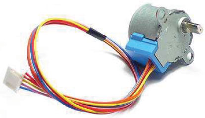
Let us take a look at this 28-BYJ48 Stepper motor.

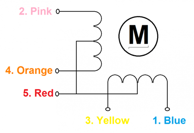
Okay, so unlike a normal DC motor this one has five wires of all fancy colors coming out of it and why is it so? To understand this we should first know how a stepper works and what its specialty is. First of all steppers motors do not rotate, they step and so they also known as step motors. Meaning, they will move only one step at a time. These motors have a sequence of coils present in them and these coils have to be energized in a particular fashion to make the motor rotate. When each coil is being energized the motor takes a step and a sequence of energization will make the motor take continuous steps, thus making it to rotate. Let us take a look at the coils present inside the motor to know exactly know from where these wires come from.

As you can see the motor has Unipolar 5-lead coil arrangement. There are four coils which have to be energized in a particular sequence. The Red wires will be supplied with +5V and the remaining four wires will be pulled to ground for triggering the respective coil. We use a microcontroller like Arduino energize these coils in a particular sequence and make the motor perform the required number of steps.
So now, why is this motor called the 28-BYJ48? Seriously!!! I don’t know. There is no technical reason for this motor for being named so; maybe we should dive much deeper into it
That is a head full of information, but we need to look at few important ones to know what type of stepper we are using so that we can program it efficiently. First we know that it is a 5V Stepper motor since we energize the Red wire with 5V. Then, we also know that it is a four phase stepper motor since it had four coils in it. Now, the gear ratio is given to be 1:64. This means the shaft that you see outside will make one complete rotation only if the motor inside rotates for 64 times. This is because of the gears that are connected between the motor and output shaft, these gears help in increasing the torque.
Another important data to notice is the Stride Angle: 5.625°/64. This means that the motor when operates in 8-step sequence will move 5.625 degree for each step and it will take 64 steps (5.625*64=360) to complete one full rotation
Calculating the Steps per Revolution for Stepper Motor:
It is important to know how to calculate the steps per Revolution for your stepper motor because only then you can program it effectively.
In Arduino we will be operating the motor in 4-step sequence so the stride angle will be 11.25° since it is 5.625°(given in datasheet) for 8 step sequence it will be 11.25° (5.625*2=11.25).
Steps per revolution = 360/step angle
Here, 360/11.25 = 32 steps per revolution.
Why so we need Driver modules for Stepper motors?
Most stepper motors will operate only with the help of a driver module. This is because the controller module (In our case Arduino) will not be able to provide enough current from its I/O pins for the motor to operate. So we will use an external module like ULN2003 module as stepper motor driver. There are a many types of driver module and the rating of one will change based on the type of motor used. The primary principle for all driver modules will be to source/sink enough current for the motor to operate.
Circuit Diagram for Rotating Stepper Motor using Potentiometer:
The circuit Diagram for the Controlling Stepper Motor using Potentiometer and Arduino is shown above. We have used the 28BYJ-48 Stepper motor and the ULN2003 Driver module. To energise the four coils of the stepper motor we are using the digital pins 8,9,10 and 11. The driver module is powered by the 5V pin of the Arduino Board. A potentiometer is connected to A0 based in whose values we will rotate the Stepper motor.
But, power the driver with External Power supply when you are connecting some load to the steppe motor. Since I am just using the motor for demonstration purpose I have used the +5V rail of the Arduino Board. Also remember to connect the Ground of the Arduino with the ground of the Driver module.
Code
#include <Stepper.h> // Include the header file
// change this to your motor
#define STEPS 32
// create an instance of the steps and pins
Stepper stepper (STEPS, 8, 10, 9, 11);
int Pval = 0;
int potVal = 0;
void setup () {
Serial.begin (9600);
stepper.setSpeed (200);
}
void loop () {
potVal = map (analogRead (A0), 01024,0,500);
if (potVal> Pval)
stepper.step (5);
if (potVal <Pval)
stepper.step (-5);
Pval = potVal;
Serial.println (Pval); // for debugging
}
video
video


No comments