
Material Required
- Arduino UNO
- LDR (Light Dependent Resistor)
- Resistor (100k-1;330ohm-1)
- LED - 1
- Relay module - 5v
- Bulb/CFL
- Connecting wires
- Breadboard
Circuit Diagram

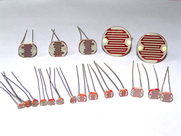
LDR
LDR is Light Dependent Resistor. LDRs are made from semiconductor materials to enable them to have their light-sensitive properties. There are many types but one material is popular and it is cadmium sulfide (CdS). These LDRs or PHOTO RESISTORS works on the principle of “Photo Conductivity”. Now what this principle says is, whenever light falls on the surface of the LDR (in this case) the conductance of the element increases or in other words, the resistance of the LDR falls when the light falls on the surface of the LDR. This property of the decrease in resistance for the LDR is achieved because it is a property of semiconductor material used on the surface.
Working of LDR controlled LED using Arduino
As per the circuit diagram, we have made a voltage divider circuit using LDR and 100k resistor. The voltage divider output is feed to the analog pin of the Arduino. The analog Pin senses the voltage and gives some analog value to Arduino. The analog value changes according to the resistance of LDR. So, as the light falls on the LDR the resistance of it get decreased and hence the voltage value increase.
Controlling Relay using LDR with Arduino

Code
#define relay 10
int LED = 9;
int LDR = A0;
void setup ()
{
Serial.begin (9600);
pinMode (LED, OUTPUT);
pinMode (relay, OUTPUT);
pinMode (LDR, INPUT);
}
void loop () {
int LDRValue = analogRead (LDR);
Serial.print ("sensor =");
Serial.print (LDRValue);
if (LDRValue <= 700)
{
digitalWrite (LED, HIGH);
digitalWrite (relay, HIGH);
Serial.println ("It's Dark Outside; Lights status: ON");
}
else
{
digitalWrite (LED, LOW);
digitalWrite (relay, LOW);
Serial.println ("It's Bright Outside; Lights status: OFF");
}
}


No comments