
Project Overview:
This project simulates a basic traffic light system using an Arduino. It controls three LEDs representing the green, yellow, and red traffic lights, cycling through them with specific delays to mimic real-world traffic lights.
How It Works:
The Arduino is programmed to sequentially light up the green, yellow, and red LEDs for specified durations. The green LED represents the "go" signal, the yellow LED represents the "slow down" signal, and the red LED represents the "stop" signal.
Components List:
- Arduino Board (e.g., Uno, Nano, etc.)
- 3 LEDs (Green, Yellow, and Red)
- 3 220-ohm Resistors
- Jumper Wires
- Breadboard (optional)
- Power Supply (for Arduino)
Software List:
Arduino IDE (Integrated Development Environment)Circuit Diagram and Connection:
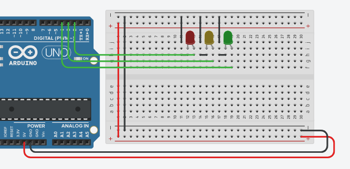
Connect the anode (long leg) of the green LED to Digital Pin 2, the yellow LED to Digital Pin 3, and the red LED to Digital Pin 4 on the Arduino.
Connect the cathode (short leg) of each LED to GND through a 220-ohm resistor.
Project Code:
int GREEN = 2;
int YELLOW = 3;
int RED = 4;
int DELAY_GREEN = 5000;
int DELAY_YELLOW = 2000;
int DELAY_RED = 5000;
void setup() {
pinMode(GREEN, OUTPUT);
pinMode(YELLOW, OUTPUT);
pinMode(RED, OUTPUT);
}
void loop() {
green_light();
delay(DELAY_GREEN);
yellow_light();
delay(DELAY_YELLOW);
red_light();
delay(DELAY_RED);
}
void green_light() {
digitalWrite(GREEN, HIGH);
digitalWrite(YELLOW, LOW);
digitalWrite(RED, LOW);
}
void yellow_light() {
digitalWrite(GREEN, LOW);
digitalWrite(YELLOW, HIGH);
digitalWrite(RED, LOW);
}
void red_light() {
digitalWrite(GREEN, LOW);
digitalWrite(YELLOW, LOW);
digitalWrite(RED, HIGH);
}
Explanation of the Code:
Variable Declaration:
int GREEN = 2;, int YELLOW = 3;, int RED = 4; define the digital pins connected to the green, yellow, and red LEDs, respectively.
int DELAY_GREEN = 5000;, int DELAY_YELLOW = 2000;, int DELAY_RED = 5000; define the delay times (in milliseconds) for each traffic light signal.
Setup Function:
pinMode(GREEN, OUTPUT); through pinMode(RED, OUTPUT); set the LED pins as outputs.
Loop Function:
The loop() function sequentially calls green_light(), yellow_light(), and red_light(), each followed by a delay corresponding to the traffic light timing.
Traffic Light Functions:
green_light() turns on the green LED and turns off the yellow and red LEDs.
yellow_light() turns on the yellow LED and turns off the green and red LEDs.
red_light() turns on the red LED and turns off the green and yellow LEDs.
Test and Troubleshooting:
Testing: Upload the code to your Arduino and observe the LEDs cycling through the green, yellow, and red signals with the specified delays.
Troubleshooting:
Ensure each LED is correctly connected to the specified digital pins.
Verify the delay times to ensure the traffic light timing aligns with your requirements.
Summary:
This project simulates a traffic light system using an Arduino and LEDs. It's an excellent introduction to sequential control in embedded systems and can be extended with more complex traffic patterns or integrated with sensors.


No comments