
Project Overview:
This project uses a light sensor (e.g., a photoresistor) connected to an Arduino to control the blinking speed of an LED. The brighter the light detected by the sensor, the faster the LED blinks. Conversely, lower light levels slow down the blinking.
How It Works:
- Light Sensor: A photoresistor (or any analog sensor) connected to the analog input pin (A0) reads the light intensity.
- LED Control: The analog reading from the sensor is used to determine the delay between turning the LED on and off, thus controlling the blink rate.
Components List:
Circuit Connection:
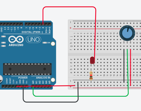
- Photoresistor Setup:
- Connect one end of the photoresistor to 5V.
- Connect the other end to A0 (analog input) and to one end of a 10kΩ resistor.
- Connect the other end of the 10kΩ resistor to GND. This forms a voltage divider.
- LED Setup:
- Connect the positive leg (anode) of the LED to digital pin 2 through a 220Ω resistor.
- Connect the negative leg (cathode) of the LED to GND.
Project Code:
int sensorValue = 0; // Variable to store the value from the sensor

void setup() {
  pinMode(A0, INPUT); // Set A0 as input for the light sensor
  pinMode(2, OUTPUT); // Set pin 2 as output for the LED
}

void loop() {
  sensorValue = analogRead(A0); // Read the value from the sensor
  digitalWrite(2, HIGH); // Turn the LED on
  delay(sensorValue); // Wait for a period proportional to the sensor value
  digitalWrite(2, LOW); // Turn the LED off
  delay(sensorValue); // Wait again for a period proportional to the sensor value
}
Explanation of the Code:
int sensorValue = 0;
- This variable stores the value read from the analog sensor, which represents the intensity of light detected by the photoresistor.
void setup()
pinMode(A0, INPUT);- Configures analog pin A0 as an input to read data from the photoresistor.pinMode(2, OUTPUT);- Configures digital pin 2 as an output to control the LED.
void loop()
sensorValue = analogRead(A0);- Reads the light intensity from the sensor and stores it insensorValue.digitalWrite(2, HIGH);- Turns the LED on.delay(sensorValue);- Keeps the LED on for a duration proportional to the light intensity.digitalWrite(2, LOW);- Turns the LED off.delay(sensorValue);- Keeps the LED off for a duration proportional to the light intensity.
How the Project Works:
- The photoresistor changes its resistance based on the light intensity. The Arduino reads the corresponding voltage at A0, which translates into a value between 0 and 1023.
- The LED’s blink rate changes according to the light detected by the sensor. In bright light, the delay is short, so the LED blinks quickly. In dim light, the delay is longer, so the LED blinks slowly.
Summary:
This project is a simple demonstration of how sensors can interact with the environment and control output devices like LEDs. It provides an introduction to analog input handling, basic electronics, and controlling outputs based on sensor data.


No comments