
1. 1. What
is SCR
An SCR, or Silicon Controlled Rectifier, is a
semiconductor, or integrated circuit (IC), that allows the control of current using a small current. Basically, it is a
simple direct current (DC) light switch.

1. 2. TYPES
OF THYRISTORS AND APPLICATIONS
#Silicon Controlled Rectifier (SCR)
Silicon controlled rectifier is normally in OFF
state but when a small current enters its gate G it goes to ON state. If the
gate current is removed the SCR remains in ON state and to turn it of the anode
to cathode current must be removed or the anode must be set to a negative
voltage in relation to cathode. The current only flows in one direction from
anode to cathode. SCRs are used in switching circuits, phase control circuits,
inverting circuits etc.

#Silicon Controlled Switch (SCS)
Working
of SCS is similar to SCR but also it can be turned off by applying a positive
pulse on the anode gate. The SCS can also turned ON by applying a negative
pulse on anode gate. The current flows only from anode to cathode. SCS are used
in counters, lamp drivers, logic circuits etc.

#Triac
Triac is similar to SCR but it conducts in both directions, means that
it can switch AC and DC currents. The triac remain in ON state only when there
is current in gate G and switched OFF when this current is removed. Current is
flowing in both directions between MT1 and MT2.

Basic SCR Applications
Basic Latching Circuit
In this circuit a SCR is used to form a basic latching circuit. S1 is a
normally open switch and S2 is a normally close switch. When S1 is pushed
momentary a small current goes into the gate of SCR and turning it ON, thus
powering the load. To turn it off we have to push the S2 push-button so the
current through SCR stops. Resistor RG is used to set the gate voltage of SCR.

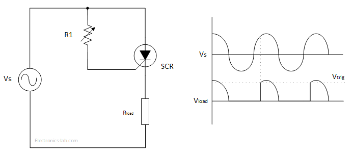
Power Control Circuit
In this circuit a SCR is used to modify a sinusoidal signal so that the load receives less power than of what would receive if source voltage was applied directly. The sinusoidal signal is applied to the gate of SCR via R1. When the voltage on the gate exceeds the trigger voltage of SCR, it goes to ON state and Vs is applied to the load. During the negative portion of the sine wave the SCR is in OFF state. Increasing R1 has the effect of decreasing the voltage applied to the gate of SCR and thus creating a lag in the conduction time. In this was the load is receiving power for less time and thus the average power to load is lower.

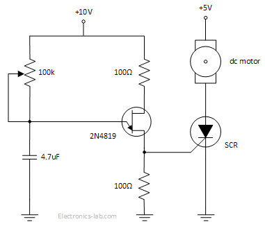
DC motor Speed
Controller
This is a variable speed DC motor controller using a UJT, a SCR and few passive components. UJT along with resistors and capacitor form an oscillator that supplies AC voltage to the gate of SCR. When the gate voltage exceeds the triggering voltage of SCR, the SCR turns ON and motor is running. By adjusting the potentiometer the output frequency of oscillator is changing and thus the times the SCR triggered is changing, which in turn changes the speed of the motor. In this way the motor is receiving a series of pulses that average over time and the speed is adjusted.

1. 3. SCR
test ?
Diode test mode sends a current through a semiconductor junction,
and then measures the junction's voltage drop. A typical silicon junction
voltage drop is 0.5_0.8 Vdc. Use the diode test mode to check diodes,
transistors, silicon controlled rectifiers (SCRs).

PDF File free downlode Click Here


No comments